4x4 Technical Support
Get answers and information about your build here. We'll do our best to help you with common questions. If you cannot find the answer you are looking for, send us an email.
Combat Axle/U-Joint Failure
To avoid or reduce axle and U-Joint failure, position the steering arm on top and allow more clearance between the springs and steering linkage. Parts Mike® offers new APM cast Dana 44 replacement "flattop" knuckles that position the steering arm .500" higher then stock GM/FSJ "flattop" knuckles. Parts Mike® APM knuckles are cast without the normal steering arm found on OEM knuckles and are drilled to use front and rear turning radius stops. This will reduce axle and U-Joint failure.
The failure occurs when the ujoint angle is allowed to go past its working limit. This is a problem with stock knuckles that only have a single stop at the front or rear or when there are no "stops" being used. The ujoint failure under hard usage usually occurs in the knuckle that is being turned away from the stop. Left wheel turned right and vice versa. We have witnessed this on numerous occasions and it made our staff start looking at the dynamics of why this was occurring. We began noticing that just before the the "ping, pop or bang" that accompanies the breakage the outside tire had been moving from side to side in what looks like a shimmy motion. The reason for this is that without a stop the weight of the tire and its motion against the axle shaft U-Joint assembly causes the tierod or other steering linkage components to flex. This allows the U-Joint to surpass and exceed its angularity limitations.
The result is broken parts that may include the balljoints that retain the knuckle. This is caused when the axles and ujoint "blowup" and "bind" creating enough pressure to force the knuckle out away from the housing. Parts Mike® APM knuckles have now incorporated 2 stops to help reduce this problem.
High Steer Done Right
Parts Mike® has High Steer steering arms, draglink/tierod links and pitman arms designed to match, or at least compromise as little as possible, the correct OEM steering angularity. This minimizes tire scrub as well as over and under steer.
For most Jeep type vehicles there is very little room between the tierod, draglink and pitman arm. To address this I have designed steering arms that have only a single hole in both left and right arms for the tierod. The draglink then intersects into the tierod 4 1/2" from the center of the steering arm taper. By using a high angle draglink end at the pitman arm this design avoids TRE bind as the end that is intersected into the tierod is able to utilize its built in motion without binding.
To address the issue of pitman arm interference with the tierod I sell a 5 1/4" pitman arm. That along with my steering arms eliminates the tendency to "rub" tierod tube against the pitman arm when the direction of the wheels is straight forward. It does this without limiting normal steering radius or changing the steering ratio.
Some companies are over-building tierod and draglink tubes. This may be useful if you are trying to push rocks or be towed by the tierod. While doing a good job of not bending the heavy duty rods relay the forces generated to the tierod or rod ends as well as the steering arms, knuckles, pitman arm and steering gear sector shaft. The sector shaft will be the weakest link in most cases, if you have beefed up the rest of the components, and will fail. Myself, I would rather bend something on the trail that I can straighten or replace. The sector shaft is not what I want broken as not too many people carry a replacement steering gear. I have found that the DOM material I furnish is very compatible with the related parts in strength.
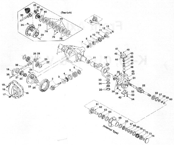
Dana 60 Front Axle Exploded View and Detailed Parts List
Identifying a T18 transmission
Ford T18
- The Ford T18 can be found in both 2wd and 4wd trucks from 1966-1986.
Early Ford T18
- Early Ford T18 rectangular case has the reverse shift lever in the case above 1st gear.
- Early Ford T18 rectangular shift cap
Late Ford T18
- Late T18 case with side leg
- Late T18 shift cap with reverse lever in cap.
- T18 different cases and caps side by side.
- The Ford T18 has a rectangular bolt pattern that measures 8 1/2" across both top holes.
- The top to bottom holes are 6 1/4" on both sides.
- The front input shaft is 10 spline x 1 1/16" and has stick out is 6 1/2" and has a tooth count of 17 or 23 teeth where it engages the cluster gear. A T18 with a 17 tooth input is the low geared (6.32-1) unit A T18 with a 23 spline input is a high geared (4-1) unit. The 6.32-1 Ford T18 will have two extra bosses cast on the front that will allow it to be installed against a GM bellhousing with relative ease.
Tie Rod and Drag Link Identification
There are many 4X4 Internet sites and companies that make reference to custom steering components and list ES2233L and ES2234R tie rod ends as being "1 Ton" parts. These are actually GM 1/2 - 3/4 ton K/V series tie rod ends used on 1976-1991 second generation vehicles.
The drag link ends ES2026R and ES2027L were used on GM 1/2, 3/4 and 1 ton K series vehicles and use a larger taper. Both of these ends have 60 degrees of motion.
GM Dana 60 1 ton front axles use the same taper through the steering arm as ES2233L and ES2234R but have a 1" X 18tpi thread; part number ES2064L and ES2011R. Dodge 4X4 W250/W350 trucks that have a 4500Lb front axle used ES2010R and L tie rod ends. Full sized Jeeps used ES453L which is the same as the ES2010R and L other then it uses a smaller diameter retaining nut.
| Part Number | Thread/Diameter | Length of Thread | Taper length | Major/Minor Diameters | Length |
|---|---|---|---|---|---|
| * Book Measurement - All others are actual measurement of parts. | |||||
| * ES2010R | .875x18tpi | 1.750" | .808 | .773 x .664 | 3.38" |
| * ES453L | .875x18tpi | 1.750" | .808 | .773 x .664 | 3.38" |
| ES2026R | .875x18tpi | 2.50" | .690 | .791 x .772 | 8.75" |
| ES2027L | .875x18tpi | 2.50" | .690 | .791 x .772 | 6.50" |
| ES2064L | 1.00x18tpi | 2.735" | .808 | .773 x .664 | 4.75" |
| * ES2011R | 1.00x18tpi | 2.00" | .808 | .773 x .664 | 4.12" |
| ES2233L | .875x18tpi | 3.75" | .808 | .773 x .664 | 9.75" |
| ES2234R | .875x18tpi | 3.50" | .808 | .773 x .664 | 4.75" |
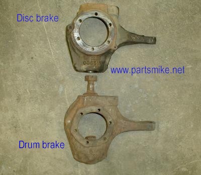
Identifying Flat Top Knuckles
The top knuckle has the correct bolt rotation and is what you want. The bottom knuckle is from a drum brake front axle and has the wrong bolt rotation. This will not work with disc brakes.
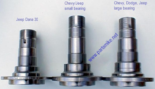
Identifying Spindles
| Part Number | Description |
|---|---|
| DAN 706537X | Dana 30 Jeep/Scout spindle |
| DAN 706528X | Dana 44 small bearing spindle |
| DAN 706570X | Dana 44 large bearing spindle |
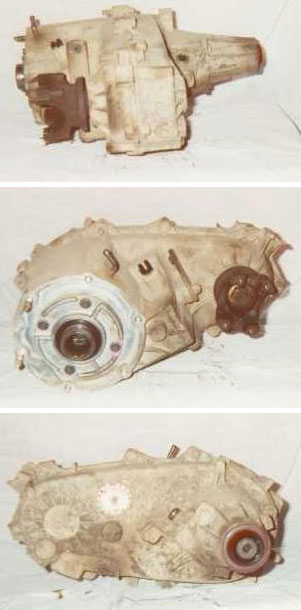
Identifying the Jeep NP231 Transfer Case
The 1987-94 models have a different bevel gear angle than 1995 and newer. There are two different front input shaft lengths, 4.125" AND 5.125". The TF999 uses the 23 spline long and the AX15 uses the 23 spline short. The Peugot AW4 up to 1990 used the 21 spline shaft and 1991 and newer used the 23 spline. All AX5 models use 21 spline.
We have the complete line of grears available in 21 and 23 spline for all 231's as well as 4 to 1 kits and Slip Yoke Eliminator kits.
Saginaw Steering Box Adjustment
The nut and screw adjust Worm bearing Preload and Sector shaft mesh. NOTE! The steering gear must be out of the vehicle to adjust it on all 1974 and later Saginaw rotary gear units. The earlier models can be adjusted (sector shaft preload) on vehicle.
This is how GM's Saginaw division recommends the adjustment be done.
- Disconnect the pitman arm from the sector shaft
- Completely back off the sector shaft adjusting screw on the sector shaft cover.
- Center steering on the "high point" then attach an inch lb torque wrench to the steering wheel shaft. The torque required to keep the shaft moving for one complete turn should be 1/2 - 2 in lbs. If the torque is not within these limits, loosen the thrust bearing locknut or tighten the valve sleeve adjuster plug to bring the preload within limits.
- Tighten the thrust bearing locknut and recheck preload.
- Slowly rotate the steering shaft several times then center the steering on high point.
- Turn the sector shaft adjusting screw until a steering shaft torque of 3-6in. lbs. more is required to move the worm through the center point.
- Tighten the sector shaft locknut to 35ft. lbs. and recheck the sector mesh adjustment. Total steering gear preload should be 14in. lbs. or less.
- Install the pitman arm and place the unit back into vehicle.
WARNING - To try and adjust the sector shaft screw without doing the preceding WILL DAMAGE the steering gear. Most of the play is not in the sector shaft adjustment, it is in the spool valve area.
How to Rebuild a T18
All T18's are basically the same. The following will allow you to rebuild this transmission while adding an adapter.
- Remove top cover, front bearing retainer and rear housing (2 or 4 wheel drive versions).
- Early "2" lever type units (identifiable by the rectangular top cover) have a tapered pin that retains the reverse shift fork located on the left side of the unit.
- Locate and drive this pin out from the front of the transmission with a small punch.
- Tap the pivot that is retained by the pin you removed out from inside of the unit.
- Remove the lever. The later T18 has 3 aluminum levers.
- Remove snap rings from both front and rear shafts that retain the bearings.
- Using a puller, remove the front and rear bearings and let the front input (maindrive) hangout through the front of the unit.
- Lift the mainshaft (output) forward and up through the top of the case.
Note that there is a thrust washer on the front end of the mainshaft. This is for the loose needle bearings in the maindrive to thrust against. DO NOT lose this washer. - Remove the front shaft up through the case.
- Remove the flat retaining plate (rear of case) that is in-between slots in the counter shaft and the reverse idler gear shaft. Note the location of the "slots" on both shafts and the direction they are pointed. They must be the same when reinstalled.
- Drive the large countershaft (cluster gear) from the front of case out through the back of the case.
- Drive the idler gear shaft out the same direction from inside the case.
- Clean, dry, and inspect all parts.
- Grease the bearings or bushing inside the idler gear and reinstall the shaft making sure the "slot" is the correct direction.
- The cluster gear has 2 rows of loose needle bearings, 4 washers, and a sleeve.
- There is a thrust washer at the front of the cluster gear and a trust washer and spacer at the back of the cluster gear.
- Use heavy grease to hold the needle bearings in place inside the cluster gear with the small washers in between the rows of needle bearings and at the end of the needle bearings where they are exposed on both ends of the cluster gear.
- Use the heavy grease to hold the front thrust washer against the case.
- Slip the rear shaft into the case with just enough of it protruding inside to hold the spacer and the rear thrust washer in place.
- Gently roll the cluster gear into position between the thrust washers and drive the large pin through the case.
- Check the direction of the "slot" before moving the shaft.
- Install the retaining plate between the 2 shafts.
- Remove the gears form the mainshaft (output) taking careful note of how they are stacked. DO NOT ATTEMPT TO SLIDE THE 1ST REVERSE GEAR (big straight cut gear) OFF THE SYNCRO HUB.
- There are 3 balls with coil springs under this gear and they will fly out and either hurt you or get lost. If you have to replace this gear you can use a couple of long metal gear driven hose clamps by clamping them over the three syncro dogs (plates under the sliding low and reverse gear). This will keep the parts from flying.
- Clean and dry the parts.
- The mainshaft you are going to use must be clean (this will be the adapter shaft if you are using one).
- Make sure that the 3rd gear thrust is the same on both original and new shafts. Some use a snap ring and thrust washer others have the thrust built on the shaft. If this is the case DO NOT try and use your old thrust washer.
- Install all gears and syncros on the new shaft.
- Using heavy grease, install the needle bearings in the maindrive (input gear).
- Put it in the case allowing it to hang out of the front.
Tip: The mainshaft with gears up so that you can slide it into the case. - Grasp the front maindrive and the rear mainshaft and push them together. Make sure the small thrust washer is in place and the 4th gear syncro ring is lined up with the 3 notches engaged with the syncro "dogs".
- Drive the front and rear bearings onto both shafts. The narrow bearing (20mm, some T18's use a wide 23mm bearing that is the same as the rear bearing) is the front bearing.
- Install the snap rings. If you have the reverse lever that goes in using the pivot (early style T18) install it now. Use a gasket sealer on the gaskets that are between the front bearing retainer and the rear adapter housing.
- Install and tighten bolts and or nuts. If you have the 2nd design 3 lever cover make sure the nylon fork pads are in place on all 3 levers.
- Use the gasket sealant for the top cover gasket and install the top cover.
- Make sure that the transmission is in neutral.
- Line up the shift forks and bolt the cover down.
- It is ready to install.
Jeep Drum to Disc Conversion
Here are step by step instruction for converting your old Jeep drum brakes to disc. Disc brake stopping power is far superior to drum and is a must for off road use. Here is what you need to do:
- J5356183 - Jeep Hub and Rotor Assembly (2)
- GM14023429 (NEW) - 1972 and later GM K series or full size jeep 1974-81 caliper support (R & L)
- RC4701 - loaded caliper (LH)
- RC4702 - loaded caliper (RH)
- LM501314 OR LM102911 - (Depends on the year of your vehicle) Replacement inner wheel bearing cup offsets the hub and rotor .062" to align with the GM caliper
- J5352688 - FSJ Brake hose or equivilent GM hose (2)
Remove the original drums, hubs, bearings, brake hoses as well as the 6 nuts that retain the spindle, do NOT remove the spindle. Remove master cylinder at firewall (non-power will require you remove pushrod under dash attached to brake pedal) or if so equipped at the power booster. Now you are ready to install.
- Bolt caliper support to the spindle using a couple of nuts
- Hang caliper on to caliper support you will notice that there is interference with the caliper and knuckle.
- Grind material from knuckle until caliper will clear
- Clean away and grindings, dirt or grime
- Remove spindle and grease inner spindle bearing
- Install spindle and bolt caliper support to spindle, tighten nuts to 28 ft/lbs
- Install hub and rotor assemblies, make sure you have installed the correct inner race, packed the bearings with high quality wheel bearing grease and installed new hub seals. Adjust wheel bearings, install locking hubs or dust covers.
- Place caliper over rotor making sure that the "bleeder" valve is at the top of caliper, install and tighten mounting pins. Leave bleeder valves open
- Attach hoses with new copper washers to calipers. Connect hose at frame and tighten steel line into the hoses
- Install master cylinder after bench bleeding as outlined in instructions that come with new master cylinders, tighten steel lines into master cylinder
- Fill master cylinder with DOT 3 fluid
- Pump brake pedal using very short strokes until you see fluid at both caliper bleeder valves, tighten the bleeder valves
- Pump brake pedal as this will align the calipers
- Bleed all brakes including rear (make sure the rear brakes are properly adjusted)
- Refill master cylinder and check for any leaks, tighten any loose fittings
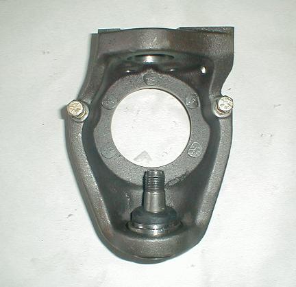
Dana 44 Knuckle Hardware Install
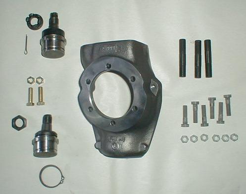
1. Custom made Dana 44 knuckle with hardware and ball joints ready to be installed.
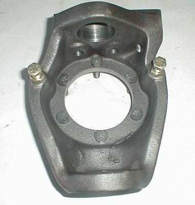
2. Install the spindle studs from the backside. You can also install the steering stop bolts and nuts at this time.
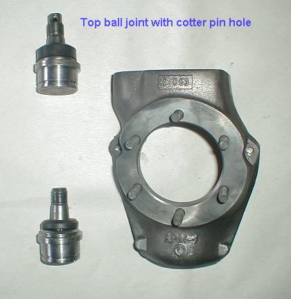
3. Knuckle with spindle studs installed. Now it is time to install the ball joints. The ball joint with the hole is the top one. The hole will be used for a cotter pin.
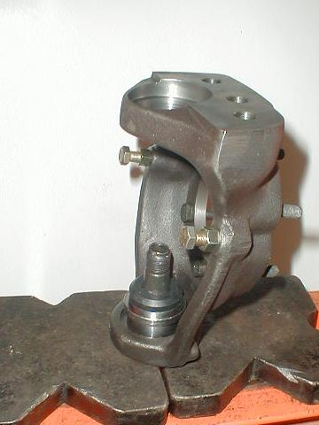
4. Install the bottom ball joint first. The ball joints are pressed in from the top of the knuckle.
5. Lower ball joint installed
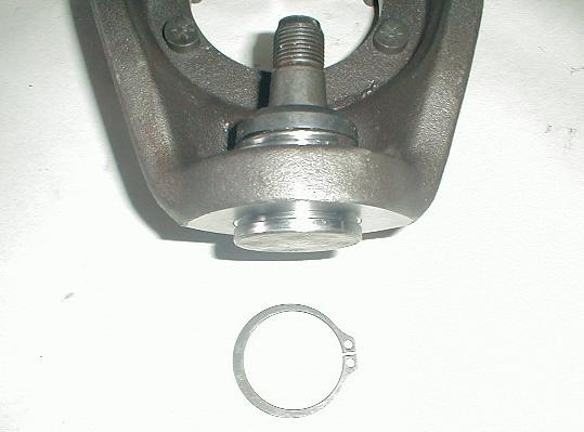
6. Install the snap ring on the lower ball joint.

7. Install snap ring on lower ball joint.
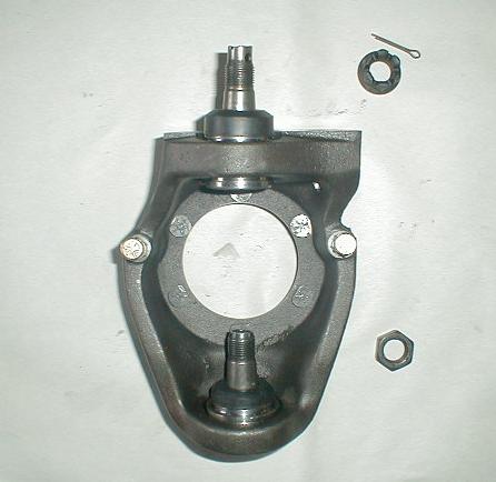
8. Knuckle with both ball joints installed. The top ball joint does not use a snap ring like the lower ball joint.
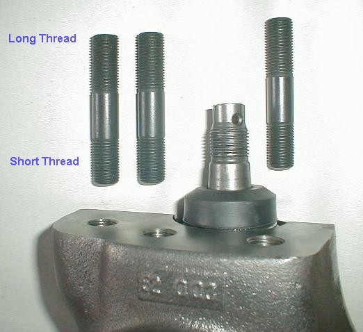
9. The high steer studs use a different thread on each end. The short thread is the end that goes into the knuckle.

10. The short thread, or dot side, on a stock GM stud, goes in the knuckle.

11. High steer studs installed in knuckle.

12. Completed knuckle
Proud Sponsors


